


The connector fits. That means nothing.
Five layers decide whether the link comes up, comes up at half, or does not come up at all, and the two that cost the most money are the ones that never report an error
- Two parts can share the same connector, fit perfectly, and still not form the link that was contracted. An interface is five layers, and all of them have to agree.
- The layers that cost the most money are the ones that report no error at all: the link comes up, monitoring stays green, and the bandwidth is half.
- Backward compatibility lives in the silicon of the switch or the adapter. The vendor documentation states that XDR transceivers cannot step down to 100G PAM4 on their own.
- A 4U XDR switch offers 144 ports of 800 Gb/s across 72 physical connectors. Count connectors and you size the equipment at half.
- How many ports a cage has depends on configuration: the single cage of the XDR adapter has eight documented arrangements, from one 800G port to two of 400G.
- Active copper with digital processing draws around 27 W per end, three times an optical link. Choosing the wrong copper costs twice what choosing the right copper saves.
The business question
An AI cluster design reached the bill of materials with 800 Gb/s nodes wired to a switch whose cage offers two 400 ports, and an 800 cable in between. The arithmetic looked like it closed.
It does not, for two independent reasons. The adapter does not add two 400 links into a single 800. And the cable specified, being from another generation, establishes no link at all. Two failures in different layers, in a design done by experienced people.
The plug fitting is the weakest of the conditions necessary for a link to exist at the rate you contracted. There are five conditions, and the two that cost the most money are precisely the ones that produce no error message.
Frame · the five layers of an interface
| # | Layer | What it decides | How it fails | What you check |
|---|---|---|---|---|
| 1 | Mechanical | whether the part enters the cage | it does not enter, or enters and overheats | IHS × RHS · OSFP × QSFP112 |
| 2 | Width | how many lanes the cage exposes | enters, comes up, half the bandwidth | 4 or 8 lanes on each side |
| 3 | Rate and modulation | Gb/s per lane and PAM scheme | fits and does not come up | 100G PAM4 (NDR) × 200G PAM4 (XDR) |
| 4 | Logic | how lanes become ports | comes up, goes green, runs at half | 1 port of 8 lanes × 2 ports of 4 |
| 5 | Optics | how lanes become fibres | wrong connector, dead link | lit fibres · MPO-12 · MPO-16 · LC |
Arraste para o lado para ver a tabela inteira.
Verification runs top to bottom. Arguing about fibre before the per-lane rate is settled wastes time, and so does arguing about rate before you know whether the part enters the cage.
Layers 1, 3 and 5 fail loudly: it does not fit, it does not come up, no light passes. Someone finds out at commissioning, with the team on site and the schedule tight, but finds out. Layers 2 and 4 fail in silence. The link comes up, monitoring goes green, and the installation runs for the next five years on half the bandwidth that was paid for.
None of this appears in the datasheet number. “800G” describes a sum. It does not say how many lanes, at what rate, grouped into how many ports, in what physical form.
Layer 1 · Mechanical: does the part fit?
Two heat-sink families share the same electrical interface and have different physical envelopes. The vendor documentation defines both. IHS transceivers, for integrated heat sink, carry cooling fins built into the plug itself and are used exclusively in switches. RHS transceivers, for riding heat sink, have a flat top and are used in network adapters and compute systems. The vendor text states that the two families are not interchangeable, because their cooling requirements differ.
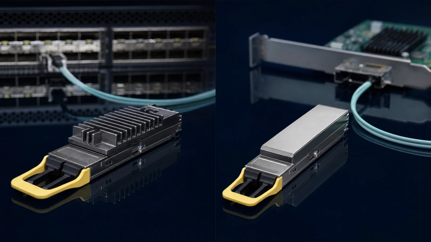
The reason is literally physical: the finned top of the IHS module is considerably taller than the opening of the single-port cage used on adapter cards. No configuration, firmware or negotiation gets around it. The part does not enter.
A recent change of vocabulary is already producing confusion on purchase orders. What the market called finned-top is now officially IHS, and what was called flat-top is now RHS. Catalogues, quotes and manuals today carry both names for the same parts.
The practical consequence shows up in splitter cables. The trunk and the legs are not interchangeable: the trunk is the switch end, in IHS, and the legs are the host ends, in RHS. Reversing them is not an assembly error anyone fixes in the field.
Layer 2 · Width: how many lanes exist on each side
A fast port does not work like a wide pipe. It is a bundle of narrow pipes running in parallel, and each of those pipes is called a lane.
The datasheet number is the sum of the lanes. A 400G link is eight lanes of 50 Gb/s, or four of 100. An 800G link is eight of 100, or four of 200. No component in that link is “an 800”.
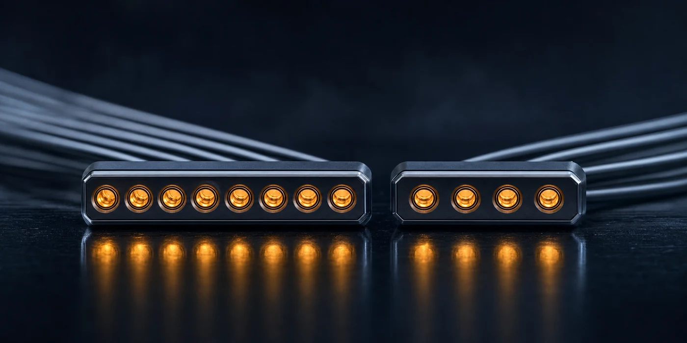
The two ends of a link frequently have different widths, and that is design, not defect. On the NDR generation the vendor documentation describes the arrangement without ambiguity: 800 Gb/s toward the switch, in eight lanes of 100G PAM4, and 400 Gb/s from the switch toward the adapter, in four lanes of 100G PAM4. The switch cage is twice the width of the host cage.
A note on vocabulary that saves argument in a meeting. The terms “OSFP112” and “OSFP224”, widely used in catalogues, are not vendor nomenclature. They are market convention for the generation of the electrical SerDes, 112 or 224 gigabits per lane, already counting error-correction overhead on top of the nominal 100 and 200. They are good enough for conversation. They are not good enough to specify with: on a purchase order, the part number is what identifies the part.
Layer 3 · Rate and modulation: the boundary between generations
This is the layer that separates NDR from XDR, and it is far more rigid than most projects assume.
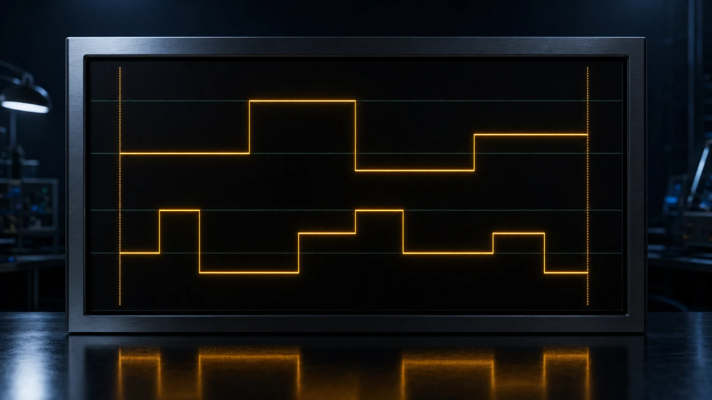
Both generations use PAM4 modulation. What changes is density: NDR runs at 100 Gb/s per lane and XDR at 200 Gb/s, doubling the throughput of each lane. Same modulation, different rate.
The vendor is explicit about the consequence, and the sentence deserves attention because it reorganises much of the buying decision: XDR transceivers cannot step down to 100G PAM4 on their own, and backward compatibility is handled at the switch or adapter level, not in the cables and not in the transceivers.
Which is to say that backward compatibility is not a property of the cable. It lives in the silicon at both ends. Buying the higher-generation module expecting it to adapt downward is the same class of mistake as buying a more expensive cable to solve a configuration problem.
Two documented situations follow. The first: an XDR module against an NDR-generation switch is not a supported scenario, there is no negotiation downward, and the vendor guidance is to use the proper NDR module rather than try to reuse the XDR one. The second is subtler and more dangerous, because backward compatibility varies between models in the same family. A 2U XDR switch handles 40, 56, 100, 200, 400 and 800 Gb/s per port, with declared compatibility for 400G NDR cables and transceivers. The 4U, same generation and same catalogue, accepts only selected NDR cables and transceivers. That is restricted backward compatibility, and assuming it from the family name is expensive.
Layer 4 · Logic: how many ports does this cage have?
A 4U XDR switch offers, according to the vendor manual, a radix of 144 ports of 800 Gb/s across 72 physical OSFP connectors. Each connector houses two transceiver engines, in the arrangement the industry calls twin-port.
The same pattern already existed in the previous generation. The documentation describes two 400 Gb/s ports inside a single OSFP switch cage, with 800 Gb/s of aggregate electrical rate, each port terminating in its own optical connector.
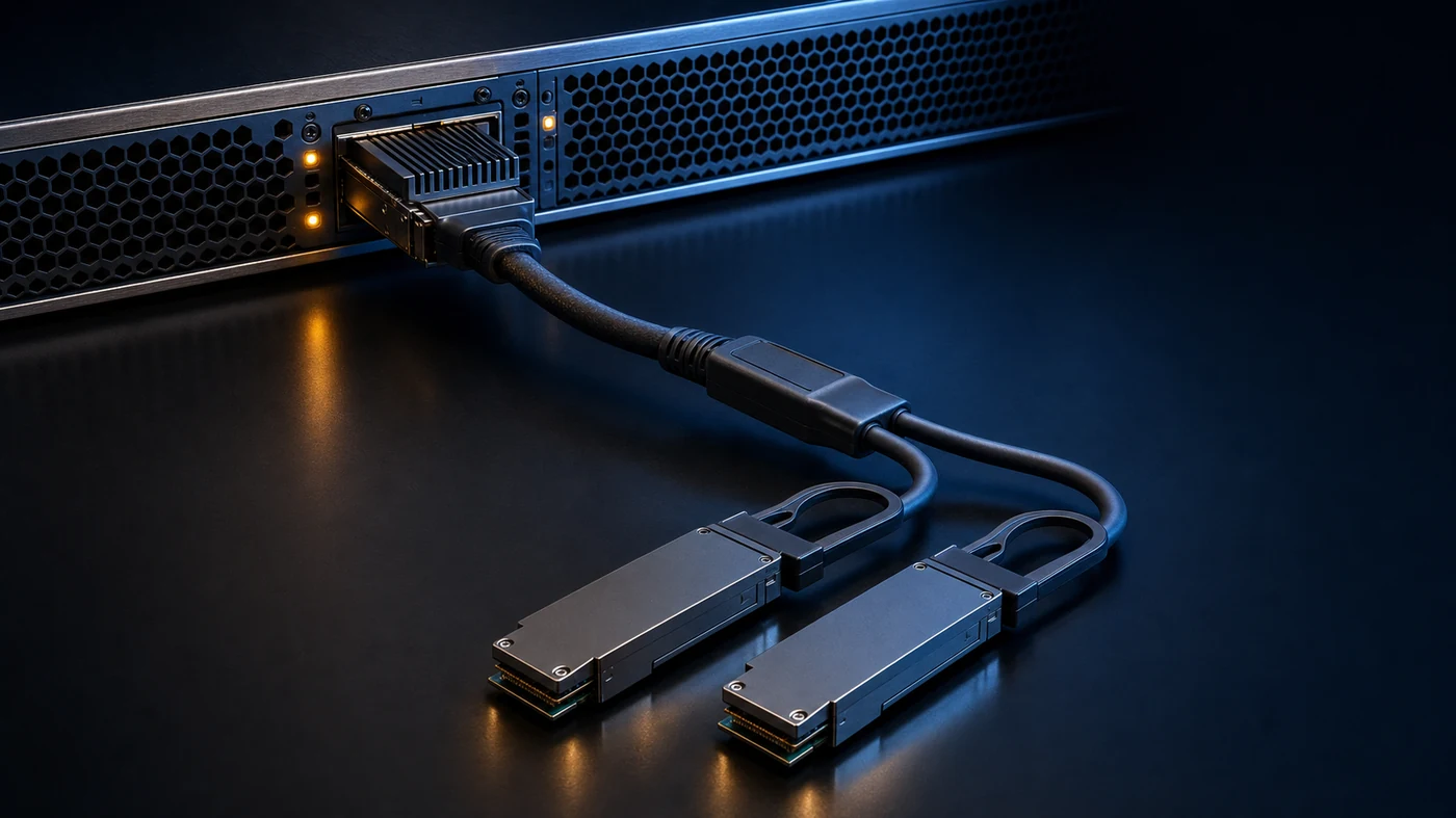
Count cages instead of ports and you size the switch at half. Order fibre by counting ports and you order half the connectors. Both errors surface late.
The deeper point, though, is on the other side of the link. The single cage of an XDR adapter does not have a fixed number of ports. It has eight documented configurations, applied by the vendor’s own command. Among them are one InfiniBand port of 800 Gb/s, which is the factory default; two ports of 400 Gb/s in XDR400 mode, with two lanes of 200G each; and two ports of 400 Gb/s in true NDR, with four lanes of 100G each.
The two “400G” modes above are not equivalent, and the vendor names the first one distinctly precisely to keep them apart. Two devices can agree on the number 400 and be describing electrical arrangements that are incompatible with each other.
One qualification matters: those eight arrangements are documented for the adapter as a standalone card. When the same silicon arrives soldered onto the system board, in the arrangement the vendor calls planarized, public documentation does not say whether all of them remain available. We return to this at the end.
How many ports a cage has is therefore a question of configuration before it is a physical fact. That is what makes this layer silent, like the second: nothing in it stops the link from coming up. It only decides how much of it comes up. Before closing the topology, confirm which configuration each end will run and whether both chose the same one. That information is not in the product brief. It is in the configuration manual.
Layer 5 · Optics: how lanes become fibres
Nobody buys “a cable”. You buy fibres, in a specific connector, with a specific polarity. The rule is derivable from the name of the variant, because each parallel optical lane uses one fibre to transmit and one to receive. The long-reach variants escape that count because they multiplex several wavelengths onto a single fibre:
- SR8 · 8 lanes · 16 fibres in an MPO-16 · 100 m on OM4
- DR4 · 4 lanes · 8 lit fibres of an MPO-12 · 500 m by the clause
- FR4 · 4 multiplexed lanes · 2 fibres in an LC duplex · 2 km
- LR4-6 · 4 multiplexed lanes · 2 fibres in an LC duplex · 6 km by the clause
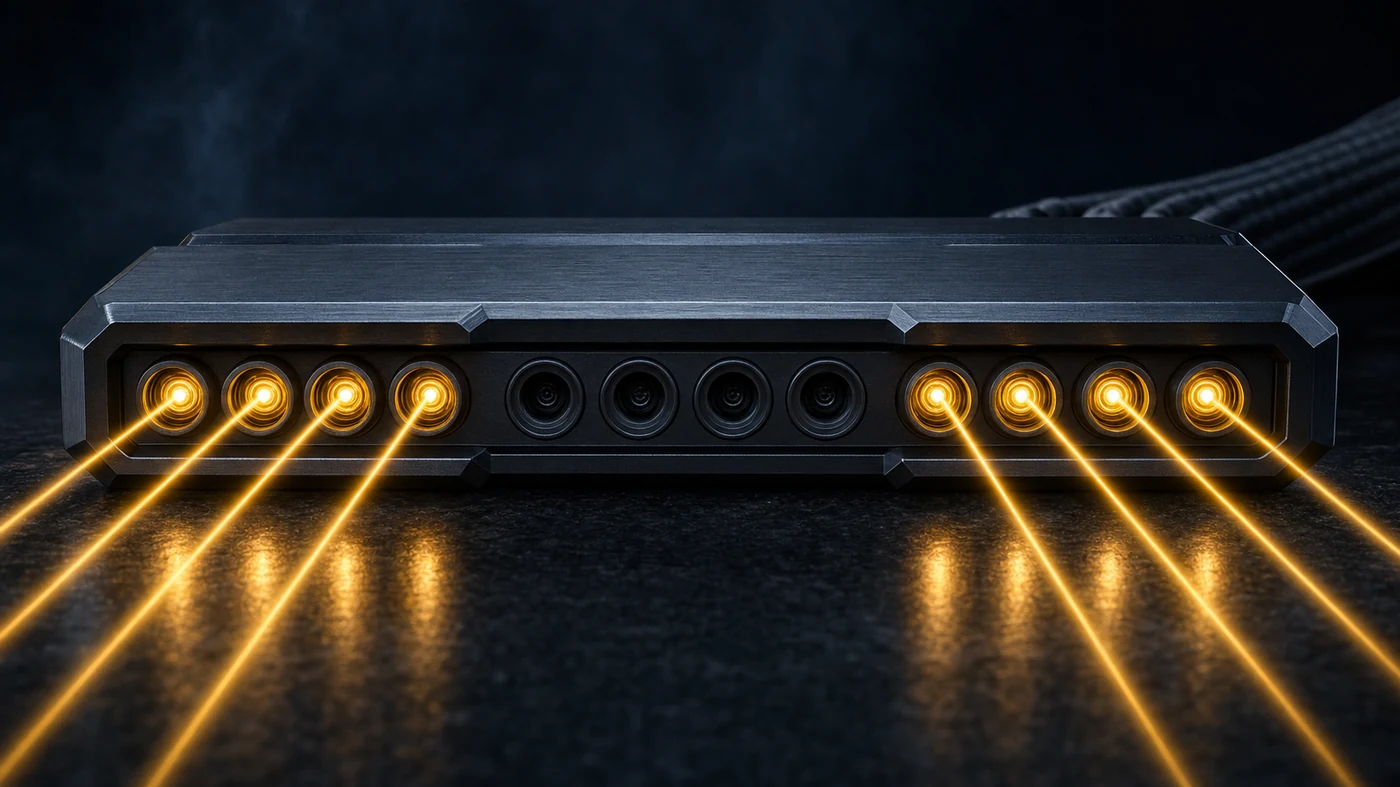
An MPO-12 does not light twelve fibres. In a four-lane variant, eight are in use and four stay dark, which means installing, documenting and managing twelve to use eight. At scale that becomes kilometres of dark fibre in the inventory.
Going up the list, the fibre count falls instead of rising. Going further does not take more cable. It takes multiplexing.
The reaches above are those of the clause, and the module you buy may be qualified for less. The datasheet of a single-port DR4 transceiver declares a maximum reach of 100 metres, against the 500 of the variant, because it assumes two patch panels in the path. The same rule as layer 1 applies: the number that decides is the one on the part, not the one in the name.
And “LR4” does not mean 10 km in the standard. The variant standardised by IEEE 802.3cu is called 400GBASE-LR4-6, and the number in the name is the reach: at least 6 km, with a loss budget equivalent to 10 km. The market almost always calls it simply “LR4” and sells modules qualified for 10 km, which meet the 6 km requirement and exceed it. The practical consequence is that real reach comes from the module datasheet, not from the name of the variant.
Where copper still wins, and where it loses badly
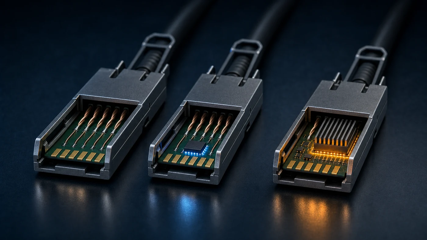
Under the label “copper cable” live three parts with very different power draw. The two numbers that decide come from the network vendor; the third is declared below.
Passive DAC has no electronics at all: conductor pairs and a contact. A cabling vendor datasheet puts the draw at around 0.1 W per end; the network vendor publishes no figure and treats the value as negligible. LACC uses low-power linear amplifiers to extend reach, at about 4 W per end. AEC uses digital processors at both ends to restore and retime the signal, drawing approximately 27 W per end.
The term of comparison: a single-port 400G NDR transceiver draws 9 W maximum with four active channels, and 5 W with two.
A copper cable with digital processing therefore draws about three times what a complete optical link draws. Copper is not a synonym for economy. These are three different decisions that the market sells under one name.
The math that decides
A reference system, with every assumption declared and replaceable.
Twelve racks, each with eight 4U liquid-cooled servers, a baseboard of 8 latest-generation GPUs and eight InfiniBand ports of 400 Gb/s per node, plus the leaf switches at the top. Two-level fat-tree, no oversubscription, which gives 96 nodes, 768 compute links and 768 uplinks. IT load of 15 kW per node, that is, 120 kW per rack and 1,440 kW in total.
Power draw, from the vendor: 9 W per end for the 400G optical transceiver, 27 W for AEC and 4 W for LACC; for passive DAC, 0.1 W per end, from a third-party datasheet. PUE of 1.54, the 2025 weighted global average from the Uptime Institute. Continuous operation, 8,760 h/yr. US industrial tariff at 8.71 ¢/kWh, preliminary May 2026 data from the EIA; the last closed year, 2024, came in at 8.13 ¢/kWh.
Interconnect layer power, by choice of intra-rack medium
(the 768 uplinks stay optical: 13.8 kW in every case)

  passive DAC          →   0.2 kW  +  13.8  =  14.0 kW
  linear LACC          →   6.1 kW  +  13.8  =  20.0 kW
  400G optical         →  13.8 kW  +  13.8  =  27.6 kW
  AEC with DSP         →  41.5 kW  +  13.8  =  55.3 kW

Against the all-optical design
  passive copper  −13.7 kW   −0.95% of IT   ≈ US$ 16.1k/yr
  linear copper    −7.7 kW   −0.53% of IT   ≈ US$  9.0k/yr
  copper with DSP +27.6 kW   +1.92% of IT   ≈ US$ 32.5k/yr more

Passive copper, over five years            ≈ US$ 80k
There is an unintended symmetry in those numbers that sums up the entire argument: choosing the wrong copper costs roughly twice what choosing the right copper saves. The decision that matters is not between copper and fibre. It is between the three coppers, and the distance between those answers is larger than the distance between the two categories.
The 13.7 kW on the first line is almost an entire node of this cluster, energised permanently and calculating nothing.
Two caveats. Not every intra-rack link fits inside the reach of passive copper, and with 4U nodes stacked the lower ones already call for LACC, so the realistic design sits between the first two lines of the table. And this is a model of declared assumptions, not a field measurement. Redo the arithmetic with your own numbers before using it in any decision.
The long-term trend pushes in the same direction. Work by researchers at IBM Research, published in the Journal of Optical Communications and Networking, projects the network going from a few per cent of datacentre power at the 10 Gb/s generation to more than 20% at the 800 Gb/s generation.
How to validate before you sign
One check per layer, in the order you check them. It fits inside a design review meeting.
Mechanical. Is each end IHS or RHS? On a splitter cable, the trunk goes in the switch and the legs in the hosts. Confirm the part numbers reflect that.
Width. How many lanes does the cage on each side expose? If they differ, that is expected, but it has to be in the drawing and not in the head of whoever drew it.
Rate and modulation. Do both sides run at the same per-lane rate? If they are from different generations, where exactly is backward compatibility implemented: in the switch, in the adapter, or nowhere?
Logic. Which configuration will each end run, and how many ports does that create? If the switch cage is twin-port, who occupies the other half?
Optics. How many lit fibres, in which connector, and is the declared reach the one for the straight arrangement or the one for the splitter?
The check that closes all the others is the vendor’s official compatibility matrix, which cross-references module class against compatible switches and adapters. Do not trust the product name, and do not trust the fact that the plug fits. One practical observation about that matrix: it is published as a web page, with no visible version number or date, so it is worth keeping a dated copy when citing it in a project document.
Common specification mistakes
Counting cages instead of ports, at layer 4. Seventy-two connectors, one hundred and forty-four ports. It undersizes the switch by half, and the error tends to appear once the rack has already been bought.
Expecting the cable to bridge the generation gap, at layer 3. It does not. Backward compatibility lives in the silicon at the two ends and may simply not exist for that combination.
Treating active copper as a single category, at layers 2 and 3. Between the linear and the digitally processed there is almost seven times the power draw, and the second spends more than fibre.
Reversing trunk and legs on a splitter cable, at layer 1. The finned module does not enter the adapter cage, and no adjustment corrects that in the field.
Assuming backward compatibility from the family name, at layer 3. Two switches of the same generation can have different policies, one broad and the other restricted to selected parts.
What is still unknown
We did not locate, in the vendor documentation, a published power figure for the optical modules of the XDR generation, 800G and 1.6T. The range of 16 to 20 W circulates in third-party catalogues and remains a market range, with no attribution to a datasheet. That is why the arithmetic in this text was done on the NDR generation, where the number is official.
The network vendor also publishes no figure for passive DAC. The 0.1 W used in the calculation comes from a cabling vendor datasheet, and the calculation is insensitive to it: even at zero, the result moves a little over 1%.
We do not know whether the eight cage configurations survive planarization. When the adapter stops being a standalone card and arrives soldered onto the system board, two sources from the same vendor contradict each other: the product specification table lists auto-negotiation for NDR, four lanes of 100G, while a staff answer on the official forum states that NDR is not supported on the planarized adapter. A forum post is not a datasheet, it carries no version number and no revision date, so we record the divergence instead of picking a side. The practical difference is large: on the same NDR switch, eight links of 400G per node, or sixteen.
Nor do we know, for a specific planarized board, whether passive copper is cleared. The validated cable list carries the caveat that using copper on a mezzanine board platform requires vendor approval for that product architecture, and the path endorsed in public answers is optical. It is layer 1 again, with the electrical path inside the server entering the link budget.
Fitting is the weakest of the five conditions. Walking the layers before approving a topology costs one review meeting; discovering the mismatch afterwards costs whatever has already been bought. Three of the five warn you, one way or another, when the two sides disagree. The other two let the link come up, light the green indicator on the dashboard, and charge the difference every month for the rest of the asset’s life.
Sources
- Optical Transceivers and Cables for AI Networking — FAQ and compatibility matrix nvidia.com ↗ verified on 08/21/2026
- Introduction | NVIDIA Q32xx and Q34xx XDR 800Gb/s InfiniBand Switch Systems networking-docs.nvidia.com ↗ verified on 08/21/2026
- Specifications | NVIDIA Q32xx and Q34xx XDR 800Gb/s InfiniBand Switch Systems networking-docs.nvidia.com ↗ verified on 08/21/2026
- Port Configurations | NVIDIA ConnectX-8 SuperNIC User Manual networking-docs.nvidia.com ↗ verified on 08/21/2026
- Specifications | NVIDIA ConnectX-8 SuperNIC User Manual networking-docs.nvidia.com ↗ verified on 08/21/2026
- MMS4X00-NS400 400Gb/s Single-port OSFP Single-mode DR4 Transceiver docs.nvidia.com ↗ verified on 08/21/2026
- LinkX Cables and Transceivers Guide to Key Technologies docs.nvidia.com ↗ verified on 08/21/2026
- Expanding Singlemode Fiber Capabilities in Ethernet Applications — IEEE 802.3cu standards.ieee.org ↗ verified on 08/22/2026
- IEEE 802.3cu aims to expand standardized 100 Gb/s and 400 Gb/s singlemode fiber capabilities (Nowell, Task Force Chair) mentor.ieee.org ↗ verified on 08/22/2026
- IEEE 802.3 Standards Activities — 400G ethernetalliance.org ↗ verified on 08/21/2026
- Optics enabled networks and architectures for data center cost and power efficiency (Taubenblatt et al., IBM Research) osti.gov ↗ verified on 08/21/2026
- Electric Power Monthly, Table 5.3 — Average Price of Electricity to Ultimate Customers eia.gov ↗ verified on 08/21/2026
- Global Data Center Survey 2025 datacenter.uptimeinstitute.com ↗ verified on 08/21/2026
- Validated and Supported Cables and Switches | NVIDIA ConnectX-8 SuperNIC networking-docs.nvidia.com ↗ verified on 08/22/2026
- ConnectX-8 XDR to QM9700 Connectivity (staff answer, official developer forum) forums.developer.nvidia.com ↗ verified on 08/22/2026
Product-specific values must be verified against the manufacturer documentation corresponding to the specification date. This document does not replace the equipment datasheet.